COBB · Technical guide
How to obtain sharp images with an industrial videoscope
Distance, lighting and depth of field: improving image quality during inspection.
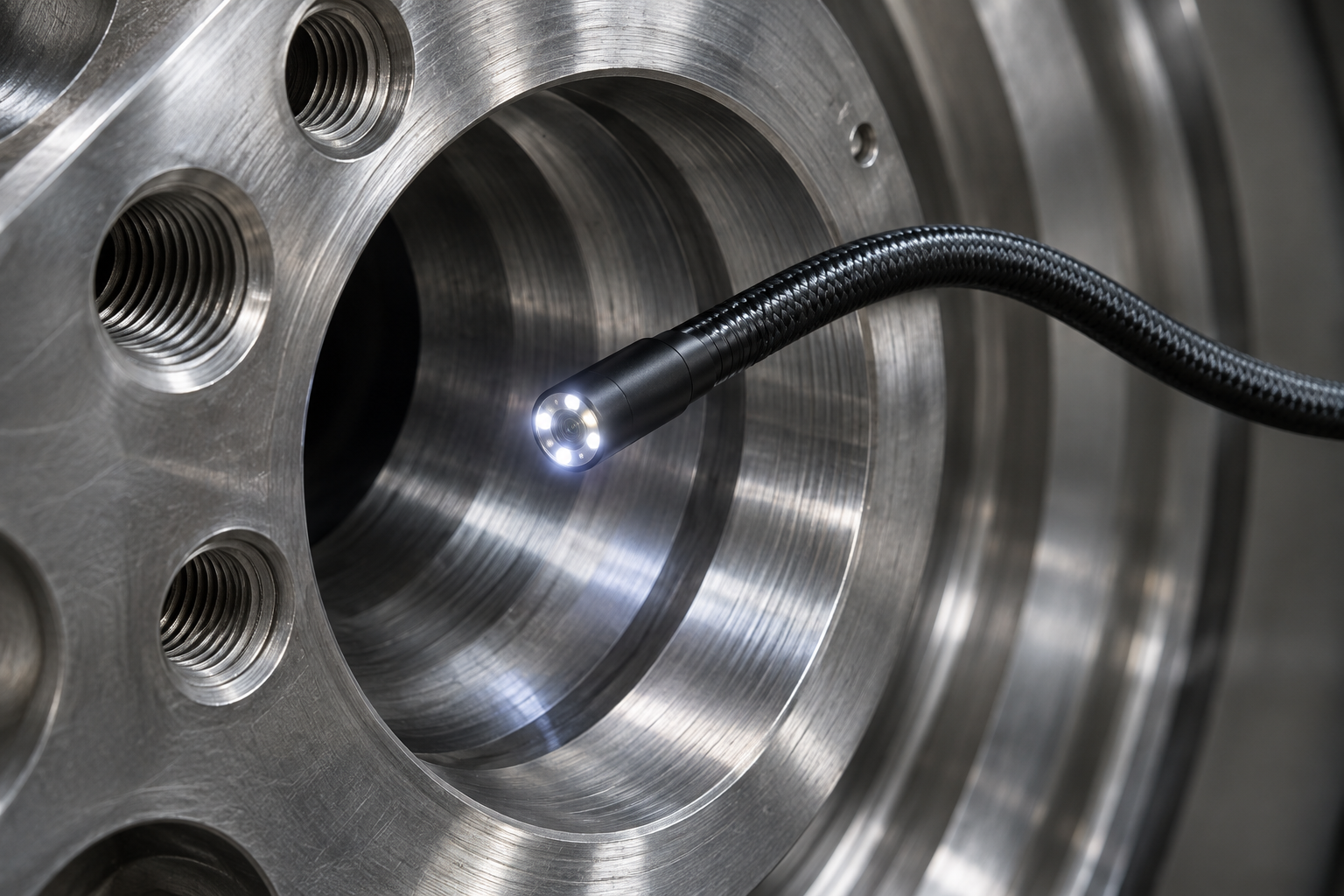
During an industrial inspection, reaching the inspection area is only the first step. To examine an internal surface and document its condition, you need clear images: the feature must be in focus, properly illuminated and viewed from a suitable direction.
What should you check when a feature looks blurred, too bright or difficult to interpret? Viewing distance, lighting and optical configuration are the first factors to consider. COBB instruments provide practical examples of how these parameters affect an inspection.
01Depth of field: distance matters
Depth of field is the range of distances within which the optics can show an object in focus. Moving the probe tip closer to the surface may help frame a feature, but the minimum distance specified for that configuration must be respected.
The COBB GTD6.0 / DUAL VISION videoscope is one example. Its technical page lists two different ranges:
| Viewing mode | Depth of field |
|---|---|
| Front view at 0° | From 10 mm to infinity |
| Side view at 90° | From 5 to 100 mm |
The useful viewing distance therefore changes even when switching between the two cameras on the same instrument. Before assessing a feature, consider which optics you are using.
The term “to infinity” describes the focusing range: the actual visibility of a small feature also depends on distance, illumination and the size of the feature itself.
02Lighting: adjusting it to the surface
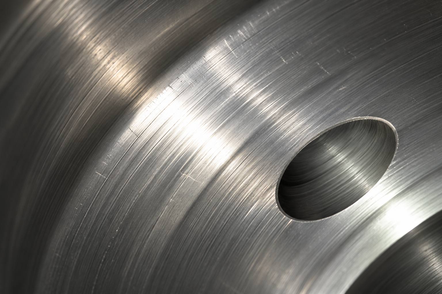
Inside a cavity, lighting must make the area being examined clearly visible. If the image contains very bright areas or reflections that obscure a feature, check the light intensity and the position of the probe tip.
The COBB NZQ range uses different lighting solutions depending on probe diameter: integrated LEDs for Ø2.0 and Ø2.8 mm, and high-power LEDs with fibre optic light transmission for Ø3.9 and Ø6.0 mm. Brightness is adjustable.
The NZQ Dual Light model uses a rear-mounted LED light source with fibre optic transmission and nine brightness adjustment levels.
In practice, adjust the lighting gradually and compare the results on screen. If a reflection persists, changing the viewing position may help reveal the surface.
03Viewing direction and field of view: two different features
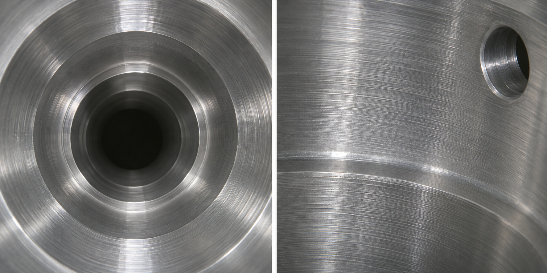
Viewing direction describes where the camera looks relative to the probe axis. Field of view describes the angular width of the image.
On the GTD6.0 / DUAL VISION, the front camera looks at 0° and has a 120° field of view; the side camera looks at 90° and has a 90° field of view. A button on the handle switches between the two views.
This distinction is useful when you need to examine both the insertion path and an internal wall. If a feature is poorly framed, check the viewing direction as well as the focus.
04Choosing the optics for the inspection
Before selecting a probe, consider the space available between the tip and the surface to be examined.
For NZQ Dual Light, the COBB website lists depth-of-field options of 10 to 200 mm or 50 mm to infinity, and fields of view of 90°, 120° or 140°, to be selected when configuring the instrument.
These are alternatives to select according to the application, rather than features available simultaneously on every probe. Close-up inspection and examination of a larger cavity therefore require the optical configuration to be assessed before purchase.
| Parameter | Options |
|---|---|
| Depth of field | 10–200 mm or 50 mm–infinity |
| Field of view | 90°, 120° or 140° |
| Viewing direction | Front |
05The monitor: assessing the complete configuration
COBB NZQ features a 6-inch touchscreen with a resolution of 1920 × 1080. This specification describes the display: assessing the captured image also requires consideration of the probe camera and optics.
The product page states that depth of field, resolution, lighting and maximum bending angle vary with the selected diameter and length. Instruments should therefore be compared on the basis of the complete configuration intended for the inspection.
06From images to inspection documentation
Once you have obtained a clear view, save it with information that helps identify the inspected location.
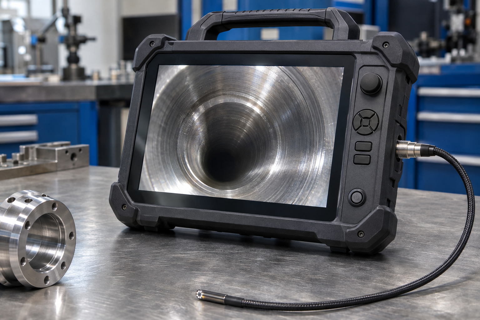
NZQ allows you to capture photos and videos, add graphic and text annotations, and compare a live image with a previously saved image.
To make the material more useful, associate images with the component identifier, the inspected area and the inspection date. Where possible, include an overview alongside the close-up to help locate the feature.
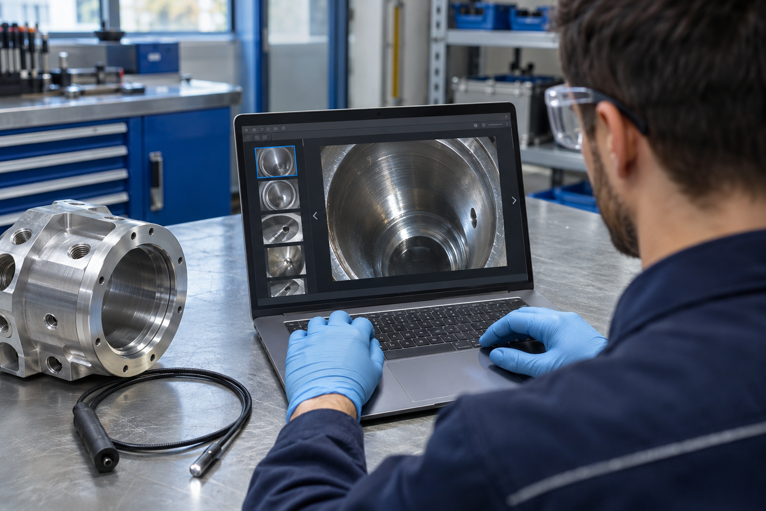
Before capturing an image
Before saving a photo or video, check:
- That the viewing distance is within the depth of field of the optics being used.
- That the lighting reveals the feature without excessive reflections.
- That the viewing direction is suitable for the surface being inspected.
- That the optics are free from contamination, following the instrument’s maintenance instructions.
- That the feature is steadily framed and can be identified in context.
- That the recording is linked to the component and inspection location.
Find the right configuration with COBB
When choosing an industrial videoscope, start with the inspection requirements: access dimensions, probe path, distance from the surface, and the need for front or side viewing.
The COBB team can help assess these factors and identify a suitable configuration.
The photographs are generated illustrations and do not depict specific COBB models. The technical values refer to the models and configurations indicated.
